I'm trying to design a lamella barrel vault approx. 30' span with 15' radius. I have very little reference info to go on, and have basically been trying to reinvent the wheel by looking at photos of other lamella projects. I have gotten sooo close, but there is always something just a little bit off when I model it in 3D, and the pieces don't join up perfectly.
I'm wondering if anyone has any specific design information for this type of roof? In particular:
- What radius is used for the lamellae?
- Which angles are used for the compound cuts at either end of each lamella?
- How is it determined where exactly the end of one lamella abuts another lamella?
15' radius and 30' span sounds like a half cylinder -- a barrel vault ? Lamella roofs I've seen have all been much broader and flatter than that, for what it's worth. The subject has been raised before and I don't recall anybody coming up with drawings or photos. The roofs I saw covered amusement park rides (Playland, Rye, NY) -- built in the 'thirties, I think.
By the way Arup tends to be very generous with their expertise ... if this is a school project, they might be willing to help you out. If it's a work project, I'm sure they'd be willing to join your team.
Eh -- I try not to throw the tread in the ditch.
First 3dh is perfect when you want a structure that will support some paneling, but please don't mistake it for some tool that you use to make some shell. It is perfect for delivering foundatons for interiour floors and walls beside foundations to attach the outher shell.
The way you seen it influence architecture has been made from a skin deep understanding abut what is possible, with a computer generated building structure -- sure it look fancy, but the most fancy thing about it, you will first realise when you understand the basics about it, and that is not about how the surface of a structure can look.
Designchick -- try open your mind and take a look at it.
Reson I not been here is this street art thing -- things progressed so gently and as some of ypu know allready, what I make is new methods explore niches sometimes difficult to expand ,such as computer generatd building structures and new forms of art. Wanna se what I produced in just a few lazy month's ;
designchick when you look closer to the side view of this, you see that the lamella don't meet with a 90 deg inbetween. If they did it would be much easier to build and cut the overlaps , but then it also would be an 3dh.
With such a structure you realy only need two standard lamella, there are no difference except in the ends of the structure where with a 3dh the endings will be easy as you work in an equal grid where all cross points will be on line. Beside you just shuld trust the computer , --- when the lamella's are drawn , they all will be alike and if you move your workplane in the 3D drawing paralell to the lamella array , then you has an accurate one to one template.
Personaly I find the Serpentine clumpsy -- there are no further newthinking in just following the tradisional front, side and top planes , and not allowing the pieces to meet at 90 deg. just mean more trouble cutting the overlaps as they will be placed different on each side of the lamella --- maybe a diamond shape looks more fancy but it's a bigger job to cut when the cut is not 90 deg.
I wonder why so much trouble to avoide the simple rules that will make a 3dh, 3dh is just a way to produce such a structure as simple as possible, it has nothing to do with the design, beside 3dh offer so much more in terms of what you much easier, can get a structure for.
The Serpentine pavilion would have been so much more smooth, if they hadn't followed the tradisional construction planes.
why don't you just contact the rural studio and get their take? or, better yet, drive on out there and talk to them. there's a group building a second lamella structure out about 15 miles from the one in the article.
basically, all the cuts/angles are the same, except at the ends (as someone pointed out above). they bought a machine (theirs was used and around 10K) to put it up - basically, it's a big formwork machine that can vary the radius and can be wheeled down the line as you lay out the roof. the process, as the kids explained, is that you have to lay the wood out, measure the angle, take it down, do the final cut, put it back in. they estimated that they could cover one bay (roughly 8 lf) per day, with two people working.
do some more research but also try to find a fabricator in your area (if you can). they can probably teach you far more than any of us.
It is simple , look easy to build , can be build for a mile like a halve tube , just strait and can have the length you want and , that is what good you can say about it.
It's boring ,strait, easy to build -- and you get what you see, a lamella structure you has to panel somehow anyway.
And these things is exactly what I newer understood --- when it is so easy to get whatever melted forms then a halve tube is what is thought, even halve tubes connected smooth with boxes or pyramide shape , smoothing into oval morphing into square running further into a snake like tube , lifted in S's from the ground for a not so boring a mile, could be just as easy made.
Fighting to get the structure into standard easily produced lamella's that add their strength by being interconnected to all other lamella's , is a good idea, but then it all end up not in fancy norphed forms, but in one long boring Australian shed.
Sorry guy's but it's in my nature : Everything is made so easy anywaym why not make it funny just one time , it's just as easy as making it boring ,but a bit more rewarding .
"[T]he process, as the kids explained, is that you have to lay the wood out, measure the angle, take it down, do the final cut, put it back in."
That's surprising. I would have thought that, like both geodesics and 3dh, the pieces for a lamella dome or vault would be presized and cut, ready for assembly. Further, as I recall it, the intersections are essentially a T configuration, at an angle; this would presumably allow an adjustment for perfect fit as each piece is attached to its neighbor. . .?
Looking again at the Rural Studio example, I see that the attempt was made in the design to align members so that they appear to pass through each other in continuous alignment. But the lamella domes I saw years ago were not made in this way -- that is, the butting pieces did not align but were offset on either side of the member they attached to, possibly to allow them to be through nailed easily (I don't recall any joist hangers or other metal fittings). This is what I meant by "allowing adjustment for a [tight] fit."
Magnifying the ends if each piece, they carry some sort of fitting, the butt end looks like nailed to the middle of next piece, this is obviously a structure made from small equal shaped pieces, rounded at the top strait at the bottom, a unique design proving the strength of a box structure. Our old geodesics requier long stringers and these being bend and secured at site , where this wil proberly profit from being assemble ontop some sort of mold , where 3dh are pre cut and supposed to fit together by no shortcut -- or yet unproven use of inserted standard fittings replacing the overlap.
The Serpentine was also made from small pieces, -- this system looks wiser but I guess it's restricted to particular forms forms ,atleast the precut curve support only this form. Still it must be quite flxexing untill a paneling is attached, --- there a 3dh with the possibility of both out and inside paneled and a true box structure beside transverse supports for various others , is a compleatly other animal.
I seem to have had a breakthrough over the past couple of days...I had been focusing on designing the individual lamellae first and then putting the whole thing together, but that seems to be the wrong approach. I've found that by first drawing the barrel vault geometry, and dividing it into a grid, I'm able to essentially connect the dots and create equally sized lamella that meet up as they should. I'll try to post more info once I'm confident I have it figured out.
As for the actual connection, I worked that out a long time ago based on various pictures I found, and my educated guess was verified by a couple of old reference books from the 50's. The lamellae have two slots cut through the middle portion to allow bolts to go through at an angle. The abutting lamellae do not form a continuous line, but are both offset slightly from the center of the continuous lamella. This setup allows for long bolts to run through all three lamellae, and the bolts are perpendicular to the lamellae that die into the continuous lamella. This is a very typical connection detail for lamella structures, but other systems can be used as well, particularly with larger, more substantial structures. The angle formed between lamellae is meant to be between 38 and 40 degrees, although I have seen many recent examples that use a much larger angle, sometimes even 90 (not for barrel vaults though).
I was under the impression that Rural Studio had pre-fabbed all the pieces as well...I'm surprised that they determined angles in field. I suppose though that whenever you have a structure of this nature, the actual installation isn't going to fit together as well as it would on the computer. I'm hoping we can pre-fab the pieces for this project though, if it comes to fruition.
To trust the computer is the right aproach -- it is exactly the "throw a sketch" and then let the skilled worker make the solution , from what crafts they know, that is simply wrong, ,,,, when you use a computer.
Why use a computer if you don't allow it to aid with what it is realy good with, and what it is realy good with is not reaky making accounts but accurate drawings , one to one drawings.
One thing in particular in what you say, make me wonder ; these long bolts that each could hold a ton, they are only used to keep two or tree weak lamella's together --- and then when the paneling are attached, they realy isn't needed, as then a box structure is the result, and a box structure do not gain it's strength by the bolts or nails that hold the stringers together.
Nomatter how you end up , as long as you use the computer and sort of calculate the compoments within borders in a 3D drawing, you end up with something far more advanced than whatever 50's or 40's plywiid lamella ,curved or laminated . box structure. --- There are plenty of wise crafts solutions that was used in the 20's and 30's and when plywood later became a choice. But it is only when you start taking the measures from the real drawing and not fiddled on spot, that you will ralise the realy smart solutions.
Designchick -- It stands to reason that a number of identical parts, assembled identically, will result in a consistent structure -- even if that structure varies slightly from what was drawn (in height, let us say, not in span). Thus, if this potential variance is deemed acceptable, the parts may safely be calculated and prepared with confidence that an acceptable (uniform) structure will result.
"I have gotten sooo close, but there is always something just a little bit off when I model it in 3D, and the pieces don't join up perfectly."
This must rely on how you aproach the problem , -- the main concern shuld be that as a 3D deawing is a gurantie it can be build , then it must be your choice of building method that is difficult to translate into a 3D world, or you forget things like thickness ; please where do these trouble show ?
Anyway , -- just everything can be made even as a tradisional work drawing , in a 3D program. But often ine can question what the idea shuld be. If the computer is only used to make a drawing that is used exactly as the old type of drawings why even use a computer ... What I say is, that if the resulting drawing, is used to show measures that is then taken manual from the drawing -- then where are the great advanteage. I know my point can be difficult to grasp, but computers and 3D , is only cutting edge, if he drawing sort of route the fabrication of the pieces. Now the 3D drawing and the program, can in fact be made to calculate the lattrice, and the result can realy maneage an N.C. mashine to manufactor the pieces -- and this is done so fast and precice, that we don't need to uniform the building blocks, the computer can calculate each of those in an instance, you can even change scale or edit the 3D form, and the computer will instantly have calculated, what is now to be cut, to assemble into the whole.
That's where the attitude of this lamella structure collide with modern design thinking ; we don't need an invbetween anymore, to fiddle the details the computer when calculating the lattrice, do that much better than any craftsman would be able to. Systems based in the Lego idea is obsolute when we fist realise that the real efficient designs, is calculated by the computer from our rules.
I built this 12' x 20' lamella roof two years ago. All the dimensioning was worked out in Excel. I would be happy to share the methods with you (the Excel spreadsheet got trashed in a system crash).
In this case all lamellas were identical except for there being a left and a right lamella, so the fabrication part is pretty straightforward. Assembling the roof itself is also easy enough. The only tricky part is where the lamellas hit the gable ends. In theory this could be computed so that the lamellas intersected in the plane of the gable, but in reality I don't think this is very easy.
Eh -- I would emagine computing a simular roof could be done from input of the Arch the length and how wide ---- but would there be a use for an application to deliver equaly shaped lamella's for an arch roof ?
The calcus are strait forwerds esp. when lamella's are meeting at 90 deg. and a complete 3D drawing with an array of lamella's could be prduced with a bit Lisp programming, I think this would be a quite trivial kind of programming -- kind of following how one would calculate the pieces before the computer but added a 3D prove of the structure. Nice work btw.
timwarner I put in your image here, so others know what I answer --guess that's allright, it was just filtering out the link by right button "properties" check ;
Thx for fixing the pic. You're right that the width of the room, and how high you want the arch to go are the key inputs, but you still have to fiddle with the number of lamellas per arch, and the length of the room (if you want the lamellas to intersect at the ends of the space).
I have a Timber Engineering Handbook from the 50s which describes some of the engineering considerations of a lamella arch. It recommends holding the angle of intersection at about 45 degrees. If you deviate from this you need to have a very different type of connector than a simple bolt.
The actual shape of these roofs is ellipsoid. Each arch is circular, but because it's skewed 22.5 degrees a transverse section is an ellipse. At least, that's what makes the trigonometry simple!
Two refinements I didn't bother with: the upper surface of the lamella should align with the elliptical section, but the planing would have to done by hand or a CNC machine. Also each arch (i.e., string of lamellas) has a twist in it roughly equal to the skew angle, and that twist has to be absorbed at the connections -- it changes the geometry.
Interesting , ---- off-topic I would consider a laminate that would hide longvise ribs ,and placing them between two layers of sheet, glued together one could use longvise rafts glued ontop a number of thin sheets , bend round around a center support to be removed after a top sheet has glued onto the filler rafts --- such a sandwich will hold the form and there will be no need for a framework as such. But that is a compleatly other animal . --- And in the end I guess ,that if ribs was to be used, I would turn to 3dh exactly for the resons you mention ; while that draw the exact ends, the twist will be a foult of fit on one side of the ribs and not a twist, and the side views will be exactly the workplane moved paralell onto all halve the ribs ,making a full scale plot possible with eventualy a fix for the fit issue. -- Il'l be back for this tread.
that is a beautiful roof! a group of my fellow students and i are thinking of building a lamella roof for a school design/build project and was wondering if you'd be willing to share any information. the structure is similar in size to yours, probably a little bit smaller. i'm still waiting to get my hands on the 'Modern Timber Engineering' book. are there any other resources you'd recommend? thank you!
Could you get an engineer's stamp on the drawings, cheaply? That's a bit of a show-stopper for the amateur builder, as soon as he moves away from conventional structures

Lamella Roof Design?
I'm trying to design a lamella barrel vault approx. 30' span with 15' radius. I have very little reference info to go on, and have basically been trying to reinvent the wheel by looking at photos of other lamella projects. I have gotten sooo close, but there is always something just a little bit off when I model it in 3D, and the pieces don't join up perfectly.
I'm wondering if anyone has any specific design information for this type of roof? In particular:
- What radius is used for the lamellae?
- Which angles are used for the compound cuts at either end of each lamella?
- How is it determined where exactly the end of one lamella abuts another lamella?
Any info would be greatly appreciated!
You and PerCorell need to talk....
(The radius should equal the span and be at a 45º in plan, mirrored about a longitudinal axis, to start with)
Where is Per? He's been quiet for a while.
In my very short time on this forum, I have already learned that I don't want to go there :-P
I need to come up with a real design that can (and may very likely) be built, not just pretty graphics...although they would help too.
...and it's a multi-centered arch in section, of those proportions, shortened from the R=Span Angled member.
15' radius and 30' span sounds like a half cylinder -- a barrel vault ? Lamella roofs I've seen have all been much broader and flatter than that, for what it's worth. The subject has been raised before and I don't recall anybody coming up with drawings or photos. The roofs I saw covered amusement park rides (Playland, Rye, NY) -- built in the 'thirties, I think.
SDR,
Yes, I am trying to produce a barrel vault. I know it's not a common application for lamella construction, but it has been done fairly recently:
http://www.architectmagazine.com/industry-news.asp?sectionID=1006&articleID=602894&artnum=2
These two links might give you a lead to more information ...
What is a Space Structure ?
The Serpentine Gallery Pavilion 2005
By the way Arup tends to be very generous with their expertise ... if this is a school project, they might be willing to help you out. If it's a work project, I'm sure they'd be willing to join your team.
Good luck ...
a half cylinder has a 2:1 Span to radius ratio, I said they were equal.
Designchick said "I'm trying to design a lamella barrel vault approx. 30' span with 15' radius."
Eh -- I try not to throw the tread in the ditch.
First 3dh is perfect when you want a structure that will support some paneling, but please don't mistake it for some tool that you use to make some shell. It is perfect for delivering foundatons for interiour floors and walls beside foundations to attach the outher shell.
The way you seen it influence architecture has been made from a skin deep understanding abut what is possible, with a computer generated building structure -- sure it look fancy, but the most fancy thing about it, you will first realise when you understand the basics about it, and that is not about how the surface of a structure can look.
Designchick -- try open your mind and take a look at it.
Reson I not been here is this street art thing -- things progressed so gently and as some of ypu know allready, what I make is new methods explore niches sometimes difficult to expand ,such as computer generatd building structures and new forms of art. Wanna se what I produced in just a few lazy month's ;
www.ArtWanted.com/PC
Now those images most people want, are huge images like this, has to be several meter wide they are not small paintings ;
But after checking , if you regular want a good laugh, then tell me where they find it ;
http://dav.sartorialab.com/CCTV/
Ha ! And auto replay too. . .
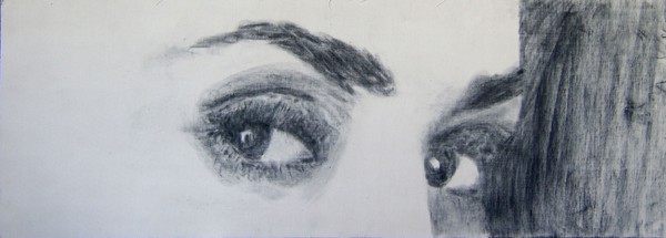
designchick when you look closer to the side view of this, you see that the lamella don't meet with a 90 deg inbetween. If they did it would be much easier to build and cut the overlaps , but then it also would be an 3dh.
http://www.architectmagazine.com/industry-news.asp?sectionID=1006&articleID=602894&artnum=2
With such a structure you realy only need two standard lamella, there are no difference except in the ends of the structure where with a 3dh the endings will be easy as you work in an equal grid where all cross points will be on line. Beside you just shuld trust the computer , --- when the lamella's are drawn , they all will be alike and if you move your workplane in the 3D drawing paralell to the lamella array , then you has an accurate one to one template.
Personaly I find the Serpentine clumpsy -- there are no further newthinking in just following the tradisional front, side and top planes , and not allowing the pieces to meet at 90 deg. just mean more trouble cutting the overlaps as they will be placed different on each side of the lamella --- maybe a diamond shape looks more fancy but it's a bigger job to cut when the cut is not 90 deg.
I wonder why so much trouble to avoide the simple rules that will make a 3dh, 3dh is just a way to produce such a structure as simple as possible, it has nothing to do with the design, beside 3dh offer so much more in terms of what you much easier, can get a structure for.
The Serpentine pavilion would have been so much more smooth, if they hadn't followed the tradisional construction planes.
.... Here I go again....
design chick -
why don't you just contact the rural studio and get their take? or, better yet, drive on out there and talk to them. there's a group building a second lamella structure out about 15 miles from the one in the article.
basically, all the cuts/angles are the same, except at the ends (as someone pointed out above). they bought a machine (theirs was used and around 10K) to put it up - basically, it's a big formwork machine that can vary the radius and can be wheeled down the line as you lay out the roof. the process, as the kids explained, is that you have to lay the wood out, measure the angle, take it down, do the final cut, put it back in. they estimated that they could cover one bay (roughly 8 lf) per day, with two people working.
do some more research but also try to find a fabricator in your area (if you can). they can probably teach you far more than any of us.
It is simple , look easy to build , can be build for a mile like a halve tube , just strait and can have the length you want and , that is what good you can say about it.

It's boring ,strait, easy to build -- and you get what you see, a lamella structure you has to panel somehow anyway.
And these things is exactly what I newer understood --- when it is so easy to get whatever melted forms then a halve tube is what is thought, even halve tubes connected smooth with boxes or pyramide shape , smoothing into oval morphing into square running further into a snake like tube , lifted in S's from the ground for a not so boring a mile, could be just as easy made.
Fighting to get the structure into standard easily produced lamella's that add their strength by being interconnected to all other lamella's , is a good idea, but then it all end up not in fancy norphed forms, but in one long boring Australian shed.
Sorry guy's but it's in my nature : Everything is made so easy anywaym why not make it funny just one time , it's just as easy as making it boring ,but a bit more rewarding .
See how easy it would be ;
"[T]he process, as the kids explained, is that you have to lay the wood out, measure the angle, take it down, do the final cut, put it back in."
That's surprising. I would have thought that, like both geodesics and 3dh, the pieces for a lamella dome or vault would be presized and cut, ready for assembly. Further, as I recall it, the intersections are essentially a T configuration, at an angle; this would presumably allow an adjustment for perfect fit as each piece is attached to its neighbor. . .?
Looking again at the Rural Studio example, I see that the attempt was made in the design to align members so that they appear to pass through each other in continuous alignment. But the lamella domes I saw years ago were not made in this way -- that is, the butting pieces did not align but were offset on either side of the member they attached to, possibly to allow them to be through nailed easily (I don't recall any joist hangers or other metal fittings). This is what I meant by "allowing adjustment for a [tight] fit."
Magnifying the ends if each piece, they carry some sort of fitting, the butt end looks like nailed to the middle of next piece, this is obviously a structure made from small equal shaped pieces, rounded at the top strait at the bottom, a unique design proving the strength of a box structure. Our old geodesics requier long stringers and these being bend and secured at site , where this wil proberly profit from being assemble ontop some sort of mold , where 3dh are pre cut and supposed to fit together by no shortcut -- or yet unproven use of inserted standard fittings replacing the overlap.
The Serpentine was also made from small pieces, -- this system looks wiser but I guess it's restricted to particular forms forms ,atleast the precut curve support only this form. Still it must be quite flxexing untill a paneling is attached, --- there a 3dh with the possibility of both out and inside paneled and a true box structure beside transverse supports for various others , is a compleatly other animal.
that rural studio project is bad-ass
I seem to have had a breakthrough over the past couple of days...I had been focusing on designing the individual lamellae first and then putting the whole thing together, but that seems to be the wrong approach. I've found that by first drawing the barrel vault geometry, and dividing it into a grid, I'm able to essentially connect the dots and create equally sized lamella that meet up as they should. I'll try to post more info once I'm confident I have it figured out.
As for the actual connection, I worked that out a long time ago based on various pictures I found, and my educated guess was verified by a couple of old reference books from the 50's. The lamellae have two slots cut through the middle portion to allow bolts to go through at an angle. The abutting lamellae do not form a continuous line, but are both offset slightly from the center of the continuous lamella. This setup allows for long bolts to run through all three lamellae, and the bolts are perpendicular to the lamellae that die into the continuous lamella. This is a very typical connection detail for lamella structures, but other systems can be used as well, particularly with larger, more substantial structures. The angle formed between lamellae is meant to be between 38 and 40 degrees, although I have seen many recent examples that use a much larger angle, sometimes even 90 (not for barrel vaults though).
I was under the impression that Rural Studio had pre-fabbed all the pieces as well...I'm surprised that they determined angles in field. I suppose though that whenever you have a structure of this nature, the actual installation isn't going to fit together as well as it would on the computer. I'm hoping we can pre-fab the pieces for this project though, if it comes to fruition.
To trust the computer is the right aproach -- it is exactly the "throw a sketch" and then let the skilled worker make the solution , from what crafts they know, that is simply wrong, ,,,, when you use a computer.
Why use a computer if you don't allow it to aid with what it is realy good with, and what it is realy good with is not reaky making accounts but accurate drawings , one to one drawings.
One thing in particular in what you say, make me wonder ; these long bolts that each could hold a ton, they are only used to keep two or tree weak lamella's together --- and then when the paneling are attached, they realy isn't needed, as then a box structure is the result, and a box structure do not gain it's strength by the bolts or nails that hold the stringers together.
Nomatter how you end up , as long as you use the computer and sort of calculate the compoments within borders in a 3D drawing, you end up with something far more advanced than whatever 50's or 40's plywiid lamella ,curved or laminated . box structure. --- There are plenty of wise crafts solutions that was used in the 20's and 30's and when plywood later became a choice. But it is only when you start taking the measures from the real drawing and not fiddled on spot, that you will ralise the realy smart solutions.
Designchick -- It stands to reason that a number of identical parts, assembled identically, will result in a consistent structure -- even if that structure varies slightly from what was drawn (in height, let us say, not in span). Thus, if this potential variance is deemed acceptable, the parts may safely be calculated and prepared with confidence that an acceptable (uniform) structure will result.
"I have gotten sooo close, but there is always something just a little bit off when I model it in 3D, and the pieces don't join up perfectly."
This must rely on how you aproach the problem , -- the main concern shuld be that as a 3D deawing is a gurantie it can be build , then it must be your choice of building method that is difficult to translate into a 3D world, or you forget things like thickness ; please where do these trouble show ?
Anyway , -- just everything can be made even as a tradisional work drawing , in a 3D program. But often ine can question what the idea shuld be. If the computer is only used to make a drawing that is used exactly as the old type of drawings why even use a computer ... What I say is, that if the resulting drawing, is used to show measures that is then taken manual from the drawing -- then where are the great advanteage. I know my point can be difficult to grasp, but computers and 3D , is only cutting edge, if he drawing sort of route the fabrication of the pieces. Now the 3D drawing and the program, can in fact be made to calculate the lattrice, and the result can realy maneage an N.C. mashine to manufactor the pieces -- and this is done so fast and precice, that we don't need to uniform the building blocks, the computer can calculate each of those in an instance, you can even change scale or edit the 3D form, and the computer will instantly have calculated, what is now to be cut, to assemble into the whole.
That's where the attitude of this lamella structure collide with modern design thinking ; we don't need an invbetween anymore, to fiddle the details the computer when calculating the lattrice, do that much better than any craftsman would be able to. Systems based in the Lego idea is obsolute when we fist realise that the real efficient designs, is calculated by the computer from our rules.
http://flickr.com/photos/13274317@N00/2699170812/ >
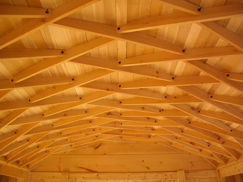
I built this 12' x 20' lamella roof two years ago. All the dimensioning was worked out in Excel. I would be happy to share the methods with you (the Excel spreadsheet got trashed in a system crash).
In this case all lamellas were identical except for there being a left and a right lamella, so the fabrication part is pretty straightforward. Assembling the roof itself is also easy enough. The only tricky part is where the lamellas hit the gable ends. In theory this could be computed so that the lamellas intersected in the plane of the gable, but in reality I don't think this is very easy.
Eh -- I would emagine computing a simular roof could be done from input of the Arch the length and how wide ---- but would there be a use for an application to deliver equaly shaped lamella's for an arch roof ?
The calcus are strait forwerds esp. when lamella's are meeting at 90 deg. and a complete 3D drawing with an array of lamella's could be prduced with a bit Lisp programming, I think this would be a quite trivial kind of programming -- kind of following how one would calculate the pieces before the computer but added a 3D prove of the structure. Nice work btw.
timwarner I put in your image here, so others know what I answer --guess that's allright, it was just filtering out the link by right button "properties" check ;
Thx for fixing the pic. You're right that the width of the room, and how high you want the arch to go are the key inputs, but you still have to fiddle with the number of lamellas per arch, and the length of the room (if you want the lamellas to intersect at the ends of the space).
I have a Timber Engineering Handbook from the 50s which describes some of the engineering considerations of a lamella arch. It recommends holding the angle of intersection at about 45 degrees. If you deviate from this you need to have a very different type of connector than a simple bolt.
The actual shape of these roofs is ellipsoid. Each arch is circular, but because it's skewed 22.5 degrees a transverse section is an ellipse. At least, that's what makes the trigonometry simple!
Two refinements I didn't bother with: the upper surface of the lamella should align with the elliptical section, but the planing would have to done by hand or a CNC machine. Also each arch (i.e., string of lamellas) has a twist in it roughly equal to the skew angle, and that twist has to be absorbed at the connections -- it changes the geometry.
Interesting , ---- off-topic I would consider a laminate that would hide longvise ribs ,and placing them between two layers of sheet, glued together one could use longvise rafts glued ontop a number of thin sheets , bend round around a center support to be removed after a top sheet has glued onto the filler rafts --- such a sandwich will hold the form and there will be no need for a framework as such. But that is a compleatly other animal . --- And in the end I guess ,that if ribs was to be used, I would turn to 3dh exactly for the resons you mention ; while that draw the exact ends, the twist will be a foult of fit on one side of the ribs and not a twist, and the side views will be exactly the workplane moved paralell onto all halve the ribs ,making a full scale plot possible with eventualy a fix for the fit issue. -- Il'l be back for this tread.
timwarner-
that is a beautiful roof! a group of my fellow students and i are thinking of building a lamella roof for a school design/build project and was wondering if you'd be willing to share any information. the structure is similar in size to yours, probably a little bit smaller. i'm still waiting to get my hands on the 'Modern Timber Engineering' book. are there any other resources you'd recommend? thank you!
I now have a SketchUp plugin that creates the cutting instructions for an arbitrarily-sized lamella roof. Let me know if you're still interested.
I could build this for you. just contact boise cascade or any other glulam manufacturer and have them make you some ribs, stand them up and fill them in and roof it.
very simple
look here
https://www.google.com/search?q=glulam&hl=en&rlz=1C1_____enUS385US385&prmd=imvns&source=lnms&tbm=isch&ei=nwCcT9XOM-GiiQKIltlN&sa=X&oi=mode_link&ct=mode&cd=2&ved=0CB8Q_AUoAQ&biw=1024&bih=653
Could you get an engineer's stamp on the drawings, cheaply? That's a bit of a show-stopper for the amateur builder, as soon as he moves away from conventional structures
i work with engineer's all the time, a stamp will be easy to obtain.
Hi gotoit. Let's talk abt this: tim@timwarner.ca
Block this user
Are you sure you want to block this user and hide all related comments throughout the site?
Archinect
This is your first comment on Archinect. Your comment will be visible once approved.